The structural analysis software RFEM 6 is the basis of a modular software system. The main program RFEM 6 is used to define structures, materials, and loads of planar and spatial structural systems consisting of plates, walls, shells, and members. The program also allows you to create combined structures as well as to model solid and contact elements.
RSTAB 9 is a powerful analysis and design software for 3D beam, frame, or truss structure calculations, reflecting the current state of the art and helping structural engineers meet requirements in modern civil engineering.
Do you often spend too long calculating cross-sections? Dlubal Software and the RSECTION stand-alone program facilitate your work by determining section properties of various cross-sections and performing a subsequent stress analysis.
Do you always know where the wind is blowing from? From the direction of innovation, of course! With RWIND 2, you have a program at your side that uses a digital wind tunnel for the numerical simulation of wind flows. The program simulates these flows around any building geometry and determines the wind loads on the surfaces.
Are you looking for an overview of snow load zones, wind zones, and seismic zones? Then you are in the right place. Use the Geo-Zone Tool to determine quickly and efficiently snow loads, wind speeds, and seismic data according to ASCE 7‑16 and other international standards.
Would you like to try out the capabilities of the Dlubal Software programs? You have the opportunity to do so! The free 90-day full version allows you to thoroughly test all our programs.
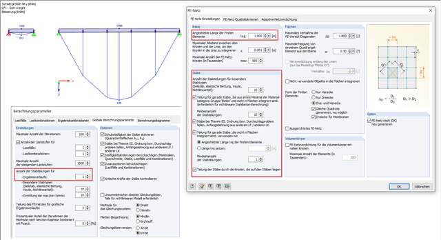
1. Member divisions for result tables
2. Member divisions
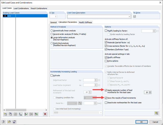
There is currently no direct way to determine the post-critical load. It is important that there are also several different states, and thus that there can be several local post-critical loads.
You can assign load increments to the structure and retroactively view the individual load increments, and thus find a load factor close to the post-critical failure (depending on the number of load increments).
In the attached model, 20 load increments and saving of the intermediate results have been set (Image 01). Image 02 shows Load Increment 10 as the last load increment before the post-critical failure, and Image 03 shows the first load increment after the post-critical failure, whereby the deformation is significantly higher.